XXX Pharmaceutical Company PTFE hollow fiber membrane deamination experiment report
Release time:
2024-04-02
Since the PTFE hollow fiber membrane can withstand strong oxidants, acids, and alkalis, chemical cleaning devices added on-site to significantly extend its service life are recommended.
1. Site overview
XXX Pharmaceutical Company's 12.5 m³/h ammonia-nitrogen-containing condensation water treatment device needs technical upgrades for its treatment project.
1.1 Inlet and outlet water status
Table 1- 1 Raw water quality
items |
index |
Remark |
Ammonia nitrogen |
2 000-3500 mg/ L |
|
C OD |
4 000 mg/ L |
|
Salt content |
3 000 mg/ L |
|
temperature |
80 ℃ |
|
Surface Tension |
7 0 mN /m |
|
Table 1-2 Effluent water quality
|
item |
Ammonia nitrogen |
|
index |
≤200mg / L |
1.2 Operating status
Currently, on-site deamination technology uses the PP membrane deamination method. The PP membrane deamination device is connected in three stages with 14 membrane modules in each stage. The raw water undergoes pretreatment to reduce the water temperature to 30°C and the turbidity to 0 5NTU. After pretreatment, ammonia nitrogen passes through the three-stage PP membrane deamination device. However, one year after the first batch of deamination membranes were operated on site, the quality of the produced water deteriorated. The ammonia nitrogen content was above 600 mg/L, which was far from meeting the effluent requirements. After replacing the deamination membranes, the second set of membrane contactors failed to function properly and experienced the same issue shortly after.
1.3 On-site problems
After speaking with the on-site personnel, it was found that the current PP deamination membrane is facing several issues, including:
1. Short lifespan of the deamination membrane
2. Broken and swollen membrane filaments
3. Not resistant to strong oxidants
4. Difficulty in achieving the required 30°C inlet water temperature in summer using a heat exchanger
5. Raw water easily permeates the membrane and enters the acid side, causing frequent acid discharge and resulting in low ammonium sulfate concentration.
1.4 Problem Analysis:
(1) The raw water has a high COD content, and the PP material is easily dissolved or swollen in non-polar organic solvents. This results in deformation or even breakage of the membrane filaments, poor hydrophobicity, and reduces the ammonia nitrogen removal rate.
(2) The hydrophobicity of the PP material is not strong enough, and the raw water can easily penetrate the membrane and enter the acid side.
(3) PP material is not resistant to strong oxidants and cannot be cleaned with strong oxidants. This results in a short life and difficulty in reuse.
(4) PP material has poor impact strength, and frequent starts and stops can easily lead to deformation and breakage of the membrane filament. SCINANO Membrane's PTFE hollow fiber membrane has obvious advantages and can better upgrade and transform on-site deamination projects.
2. Introduction to the main technical principles and characteristics of PTFE deamination membrane
2.1 Introduction to the principle of PTFE hollow fiber membrane deamination technology
PTFE hollow fiber membrane deamination technology is an innovative and highly effective method that combines physical or chemical absorption with membrane separation. To begin the process, a specific amount of alkali solution is added to the ammonia nitrogen wastewater to adjust its pH value. This creates a dissociation equilibrium of ammonia nitrogen, where NH4-+OH-=H2O+NH3. As the pH value increases, ammonia dissociates in the water. When the pH is above 11, 98% of the ammonia in the wastewater dissociates into its free state, 〖NH〗_3. After adjusting the pH value, the ammonia nitrogen wastewater and dilute sulfuric acid absorption liquid are introduced into the tube side and shell side of the membrane contactor, respectively. Since the ammonia in the wastewater has already dissociated, it will gradually volatilize from the gas-liquid interface and diffuse through the hydrophobic pores of the PTFE membrane. The ammonia gas will then enter the dilute sulfuric acid side and be absorbed. The membrane absorption process is illustrated in Figure 3-1, while the microscopic reaction process is shown in Figure 3-2.

Figure 2-1 Simplified diagram of membrane absorption process
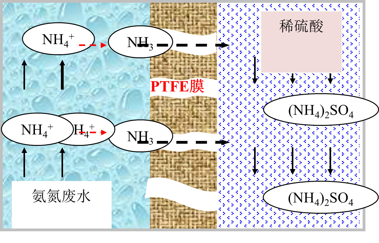
Figure 2-2 Simplified diagram of the microscopic reaction of the membrane absorption process of high concentration ammonia nitrogen wastewater
The following is a description of a hydrophobic PTFE membrane that has a hollow fiber structure. This membrane has a very high specific surface area which provides a mass transfer interface for two-phase mass transfer. Compared to other membrane materials such as PP or PVDF, PTFE material has good hydrophobicity and chemical stability, which results in a longer service life and stable operating performance.
In the traditional stripping process, high-concentration ammonia nitrogen wastewater enters the stripping tower after dissociation, and a large amount of compressed air is used for stripping. The stripped ammonia gas must enter the acid absorption tower to avoid pollution.
The membrane absorption process involves a membrane contactor that replaces the functions of both the stripping and absorption towers. The PTFE hollow fiber membrane in the contactor has a filament structure that increases the contact area and reaction efficiency, which substantially reduces the required footprint. Moreover, the membrane absorption process eliminates the risk of secondary pollution by not using air blowout, providing significant technical advantages.
The process engineering diagram can be found in Figures 3-3.
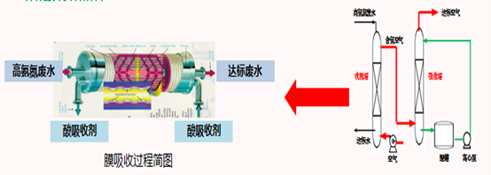
Figure 2-3 Comparison diagram of high ammonia nitrogen wastewater treatment process
2.2 Characteristics of PTFE hollow fiber membrane deamination technology
This technology has the following characteristics:
1. The microscopic combination of stripping tower + chemical absorption tower or stripping tower + neutralization reactor can realize the separation and enrichment of volatile substances in the membrane contactor at the same time. It has a high specific surface area, high mass transfer driving force, and occupies a small area. Advantages such as investment savings.
2. There is no direct contact between sewage and absorbent, the two phases are independently controlled, and there is no flooding or foam entrainment.
3. Lime can be used to adjust the pH of wastewater, reducing operating costs.
4. Near normal pressure operation, electric energy is only used to drive the material liquid through the membrane module, saving >80% of electricity.
5. After suitable pretreatment of wastewater, the operation performance is stable, and the service life is long.
6. Modular design, linear amplification, controllable effluent ammonia nitrogen value, and can be seamlessly coupled with biological treatment.
7. By-products (ammonium sulfate, ammonium phosphate, ammonium chloride, ammonia, etc.) have many types, high concentrations and purity, and can be reused, which can effectively reduce operating costs.
8. The whole process is closed to avoid secondary pollution effectively.
9. The operation is flexible and economical, especially with a small processing capacity. and it is easy to expand the capacity in the later stage.
10. PTFE hollow fiber membrane has highly stable performance and can be cleaned and regenerated.
2. 3 Core product-PTFE hollow fiber membrane
The membrane material PTFE has strong hydrophobicity, high mechanical strength, very stable chemical properties, insolubility and infusibility, corrosion resistance, resistance to organic solvents, acid and alkali resistance, and oxidation resistance. The excellent properties also make the PTFE hollow fiber membrane difficult to wet, has a long life, and other advantages. Still, PTFE materials also have shortcomings, such as difficulty in material molding and adjusting the pore structure. Only a few companies in the world can produce PTFE hollow fiber membranes. SCINANO has successfully developed a PTFE hollow fiber membrane production process and applied the product to high ammonia nitrogen wastewater treatment。
Table 2-1 Contact angle and surface energy of different materials
|
|
PTFE |
PVDF |
PP |
|
Contact angle ( degrees ) |
108-115 |
107 |
93.5±0.2 |
|
Surface energy (dynes/cm) |
18-20 |
25 |
29-31 |
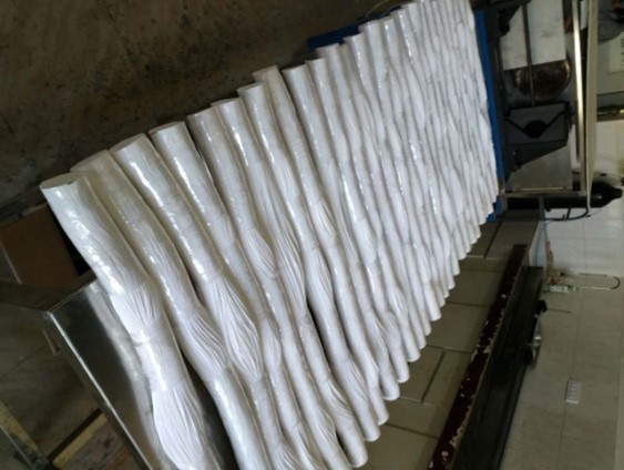
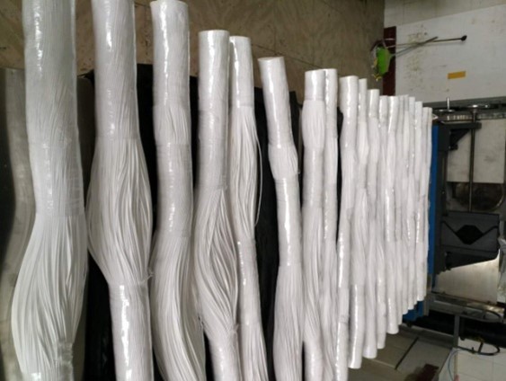
Figure 2-4 PTFE hollow fiber membrane
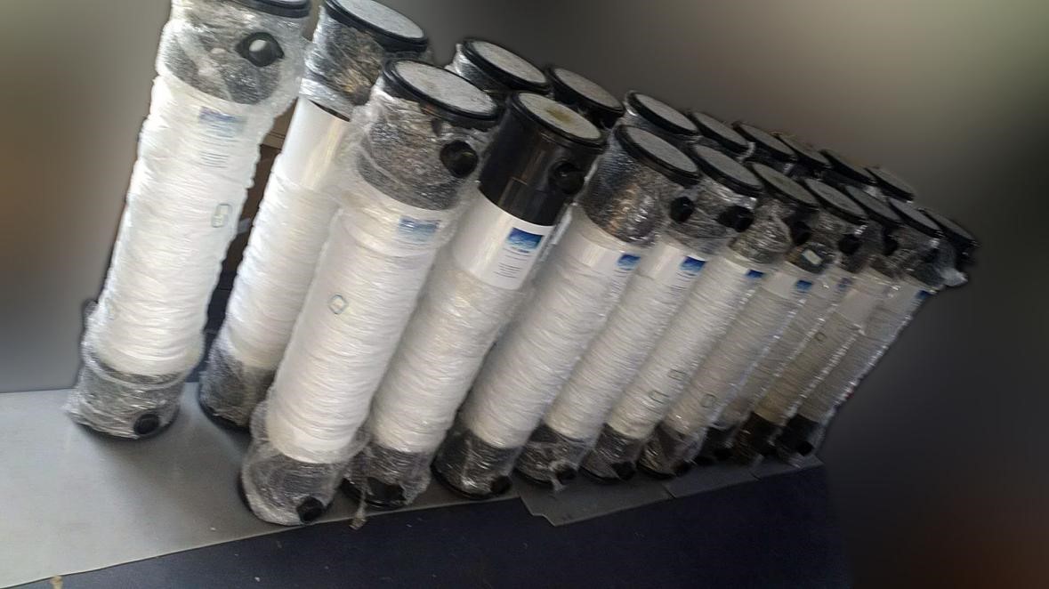
Figure 2-5 PTFE hollow fiber membrane contactors
3.PTFE deamination membrane test
3.1 Test purpose
Under different operating conditions, the removal effect of PTFE hollow fiber membrane on ammonia nitrogen-containing wastewater from XXX Pharmaceutical was explored.
Table 3-1 Test device parameters
|
PTFE hollow fiber membrane area |
1.6 m 2 |
|
series |
3 |
|
operating temperature |
3 5 - 45 ℃ |
|
operating pressure |
≤ 0.8 bar |
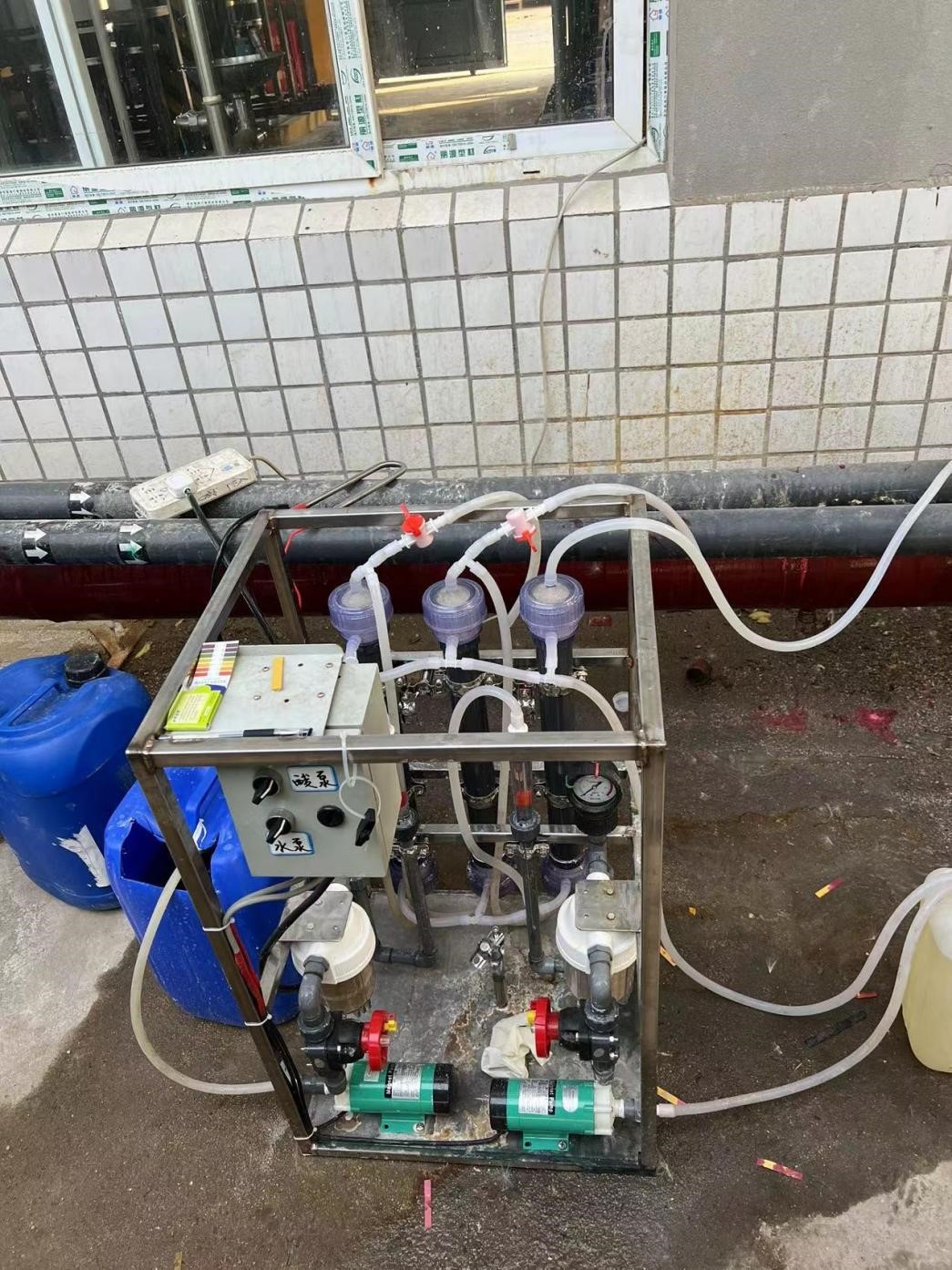
Figure 3-1 PTFE hollow fiber membrane deamination test device
3.2 Operation mode
(≥35 °C) by heating rods in the raw water barrel, and alkali is added. The water is lifted by the raw water pump and sent to the PTFE hollow fiber membrane deamination device (third stage) to remove ammonia nitrogen.
By controlling the water temperature and PH of the raw water, the flow rate of the incoming water, the PH of sulfuric acid, and the circulation flow rate, the test is carried out, and the optimal parameters of the site are determined through the test results.3.3 Test data
Table 3-2Test data table
Test date: 2 022.3.9
|
time |
water ingress |
water production |
sulfuric acid |
Remark |
||||||
|
Temperature(℃) |
Flow (L/H) |
P H |
Ammonia nitrogen ( m g/L) |
Primary ammonia nitrogen ( m g/L) |
Secondary ammonia nitrogen ( m g/L) |
Tertiary ammonia nitrogen ( m g/L) |
P H |
Flow (L/H) |
||
|
9:25 |
4 0 |
2 0.5 |
1 1.5 |
|
|
|
|
≤2 |
1 40 |
|
|
9:50 |
|
|
|
2 500 |
9 70 |
4 50 |
3 47 |
≤2 |
|
|
|
10:16 |
3 6 |
2 0.5 |
1 1.5 |
|
|
|
|
≤2 |
2 40 |
|
|
10:38 |
|
|
11.5 |
|
|
|
320 |
≤2 |
|
|
|
10:53 |
42 |
20.5 |
12 |
|
|
|
|
≤2 |
|
|
|
11:15 |
|
|
|
|
|
|
220 |
≤2 |
|
|
|
11:23 |
38 |
17 |
12 |
|
|
|
153 |
≤2 |
|
|
|
13:05 |
|
|
|
|
|
|
|
≤2 |
|
|
|
13:15 |
28 |
12 |
12 |
|
|
|
70 |
≤2 |
|
|
|
13:30 |
43 |
17 |
12 |
|
|
|
81 |
≤2 |
|
|
|
14:17 |
|
17 |
12 |
|
|
|
|
≤2 |
150 |
|
|
14:20 |
|
17 |
12 |
|
|
|
42 |
≤2 |
|
|
|
14:48 |
4 4 |
1 7 |
1 2 |
|
|
|
4 6 |
≤2 |
|
|
|
14:50 |
|
2 5 |
1 3 |
|
|
|
|
≤2 |
|
|
|
15:00 |
4 4 |
2 5 |
1 3 |
|
|
|
1 29 |
≤2 |
|
|
|
15:20 |
|
|
|
2 400 |
|
|
|
≤2 |
|
|
3.4 Data analysis
3.4.1 When the inlet water flow rate is ≤ 17L/H, the ammonia nitrogen content of the produced water is as shown in the figure below
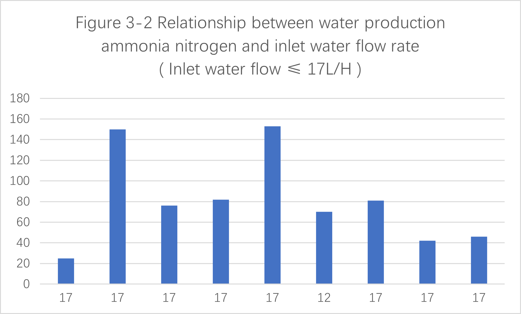
As shown in the figure above, when the inlet water flow rate is ≤ 17L/H , the ammonia nitrogen content of the produced water is less than 200 mg / L, which meets the requirements.
3.4.2 When the inlet water flow rate is >1 7L/H , the ammonia nitrogen content of the produced water is as shown in the figure below。
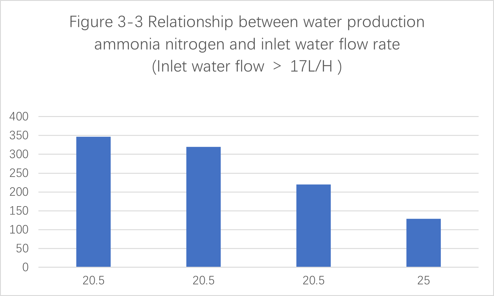
As shown in FIG
(1) When the inlet water flow is 25L /H , the ammonia nitrogen produced in the water is 129 mg/ L , which meets the requirements. At this time, the raw water pH is 13 , the sulfuric acid circulation volume is 150L / H , and the inlet water temperature is 44 ° C.
(2) When the inlet water flow is 2 0.5L/H , the ammonia nitrogen in the produced water is greater than 200 mg / L . The data is shown in the table below
|
Ammonia nitrogen in produced water (mg /L ) |
Temperature (℃) |
Raw water PH |
Acid cycle volume (L /H ) |
|
347 |
40 |
11.5 |
140 |
|
320 |
36 |
11.5 |
240 |
|
220 |
42 |
12 |
240 |
The reasons are analyzed as follows:
1pH value of the raw water is low, and the incoming water flow is large. As a result, the ammonia nitrogen in the raw water cannot be converted into ammonia gas through the membrane in time and is absorbed by sulfuric acid, increasing the ammonia nitrogen content of the produced water.
2.There may be errors in the measurement of produced water ammonia nitrogen data.
3.4.3 Analysis of PTFE hollow fiber membrane deamination absorption liquid
According to field test data, the growth rate of the absorbing liquid is approximately 2% of the original water.
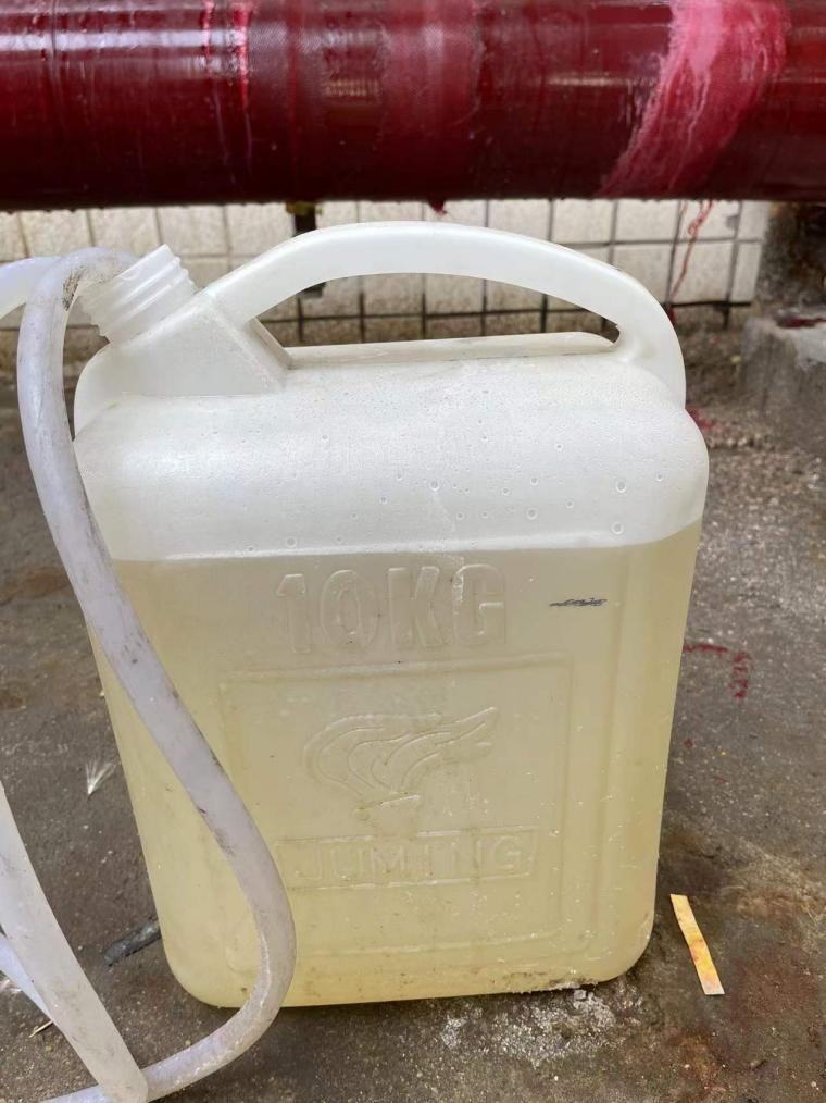
Figure 3-4 Growth amount of absorption liquid
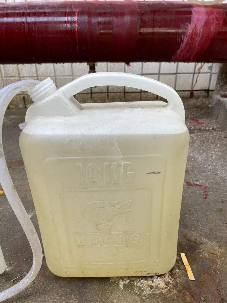
Figure 3-5 Growth amount of absorption liquid
4. Summary and suggestions
4.1 Comparison between PTFE hollow fiber membrane and PP membrane
(1) P TFE can tolerate higher organic matter and is not easy to dissolve and swell in organic solvents.
(2) P TFE can withstand strong oxidants, acids, and alkalis and can be chemically cleaned to extend the membrane life.
(3) P TFE has strong impact resistance, higher toughness, and is not easy to break.
(4) P TFE is more hydrophobic, the membrane fibers are not easily permeable to water, the removal efficiency is higher, and the ammonium sulfate concentration is higher.
(5) PTFE membrane can withstand higher temperatures and is more adaptable and energy-saving than PP membrane.
In summary, PTFE hollow fiber membrane deamination technology is more suitable for actual on-site conditions than PP membrane deamination technology.4.2 Summary
4.2.1 Operating parameters
Based on the test results and previous application cases, the recommended operating parameters are as follows:
|
Inlet water PH |
Inlet water flux (L MH ) |
Inlet water temperature (℃) |
Sulfuric acid circulation volume (L /H ) |
Sulfuric acid PH |
|
≥ 12 |
≤1 1 |
3 5-45 |
≥three times water inflow |
<2 |
4.2.2 Number of membrane groups
According to the actual situation on site and the test situation, using three-level series membrane contactors, with 18 components in each level, atotal of 54 membrane contactors is recommended.
Table 4-1PTFE hollow fiber membrane module parameter table
|
model |
Deamination membrane contactor 8 inches |
|
Component diameter |
8 inches |
|
Component length |
1200mm |
|
Membrane shell material |
UPVC |
|
Component weight (dry, wet) |
24/40(kg) |
|
membrane area |
65m 2 |
|
Membrane material |
PTFE |
|
Membrane inner and outer diameter |
1/0.5(mm) |
|
Single processing capacity |
0.5-1.5m 3 /h |
|
Single stage removal rate |
70%-90% |
|
Number of stages that can be connected in series |
3 |
|
pressure loss |
0.1bar |
|
Inlet ammonia nitrogen |
500-10000ppm |
|
Outlet ammonia nitrogen |
|
|
operating temperature |
35-45℃ |
|
operating pressure |
0.1-1bar |
|
PH |
0-14 |
|
Surface Tension |
≥60mN/m |
|
Remark |
|
4.3 Others
Since the PTFE hollow fiber membrane can withstand strong oxidants, acids, and alkalis, chemical cleaning devices added on-site to significantly extend its service life are recommended.
Latest News


